製品
Elasto-plasticity numerical test of the FRP material with consideration of crack propagation in resin/ interfacial peeling of multi-scale analysis
It is possible to define all non-linear material models held in Ansys freely to the micro model and those effects can take into account a numerical material test in the non-linear version CMAS. This analysis example introduces numerical material test that takes into account the resin internal cracking progression and interfacial peeling of the FRP fiber matrix.
Numerical material test that takes into account interfacial peeling (simple model)
It is possible to define peeling properties that were specified the critical stress in the tangential component and the normal component to contact interfaces in Ansys. Figure1 shows the outline of the fiber-reinforced composite material that is reinforced in one direction. Fibers are oriented in the direction perpendicular to the paper surface. Defining the elastic material to the fiber and the elastic-plastic material to the resin, also interfacial peeling properties to the interfacial of resin and fiber.
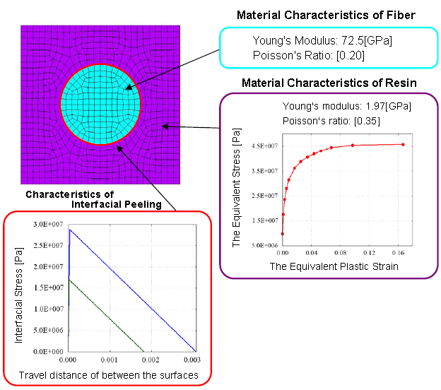
Figure1. Material Properties Value and Overview of Analysis Model
Performing pure shear and uniaxial tension tests on the numerical material test pieces that are applied to those material models. First, Figure 2 shows the results of the uniaxial tensile test. The macro material response shows both cases: considering interfacial peeling and not considering interfacial peeling. The material response does not depend on the definition whether interfacial peeling characteristics is present or absent, because the stress that promotes peeling on the material interface does not work in the uniaxial tensile test in x direction (the direction of the fiber orientation). On the other hand, interfacial peeling occurs in the uniaxial tensile test in a direction perpendicular to the fiber because the stress is acting in the normal direction of the interface. In accordance with peeling occurring, the apparent rigidity can be observed as extremely small since between the interfaces are no longer transferring stress.
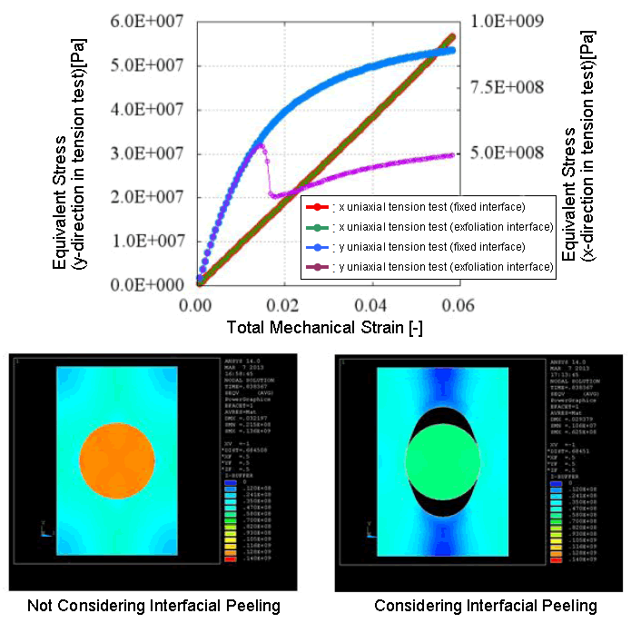
Figure2. Equivalent stress contour and macro material response during the uniaxial tensile test
Figure3 shows result of pure shear test. You can see the rapid stiffness change accompany the interfacial peeling, similar to the uniaxial tension test.
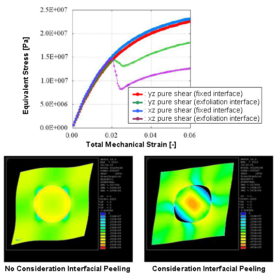
Figure3. Equivalent stress contour and macro material response during the pure shear test
So far, we have shown the example analysis results in simplified model that is modeling only one fiber. The important point here is to assume the periodic symmetry in all directions in numerical material test of CMAS. In other words, this case corresponds to the result of whole materials behavior, not only to the one fiber model. When peeling starts on the interface of the one fiber, all fiber interfaces in the whole material began peeling at the same time. Detailed analysis model, which is a more detailed expression in the unit cell with a plurality of fibers, is required in order to take into account the damage behavior conforming to the actual phenomena.
Numerical material test that takes into account the crack propagation in resin (detailed model)
Introducing an example of numerical material test that takes into account the crack propagation in resin to the model having a detailed fiber distribution. In Ansys, it is possible to perform the analysis that simulates the destruction of the element. It is possible to apply various indicators such as the maximum strain, maximum stress, or combination of those as fracture criteria. The element that reaches the specified reference value can be used to simulate the destruction by setting to lower rigidity in any ratio.
Figure4. shows the numerical material test results that take into account the destruction of the one-direction-reinforced model (but fiber positions are distributed). Element destruction occurs locally from the stress concentration location and the apparent rigidity drops. You can see the state that macro rigidity disappears (material is completely destroyed) at the stage of destruction area is progressed with increasing macro strain, and both ends of the model led to the destruction region.
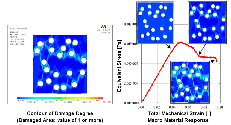
Figure4. Uniaxial tensile numerical material test that takes into account the crack propagation in resin
Analysis Types
Numerical Material Test, Elasto-plastic Analysis, Damage Analysis
関連情報
関連する解析事例
MORE



関連する資料ダウンロード
MORE-

【全記事】CAEのあるものづくり vol.43
ユーザー様インタビュー記事8件を1冊に集約した保存版
-

【カタログ】3Dデザインソリューション
-

設計者CAEを”使われる仕組み”にするには?
アルパイン設計事務所様に学ぶ、Ansys Discovery 定着の実践事例
-
熱流体システム全体を高速解析ーFlownex Simulation Environmentー
-

金型設計から量産までをIoT生産データでつなぐ一気通貫のものづくり
-
実形状ベースのCAEソリューション
~CTデータを活用した高精度シミュレーション~
-
患者CTデータを治療シミュレーションへ
~個別化医療を支える解析活用ソリューション~
-
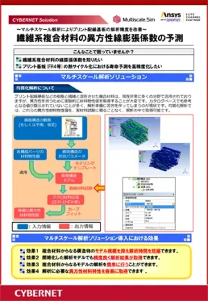
繊維系複合材料の異方性線膨張係数の予測
~マルチスケール解析によりプリント配線基板の解析精度を改善~