製品
Large strain numerical material test of fiber-based composite material using advanced element formulation
Convergence problem of the numerical material test in composite material
Figure 1 shows modeling of composite material reinforced in one direction by fibers which are oriented perpendicular to the plane. There is a difference in rigidity of about three orders of magnitude between the matrix and fiber.
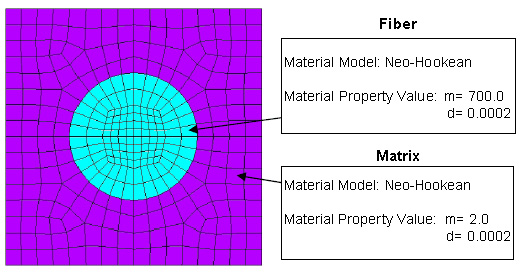
Figure 1. Fiber-based composite material reinforced in one direction
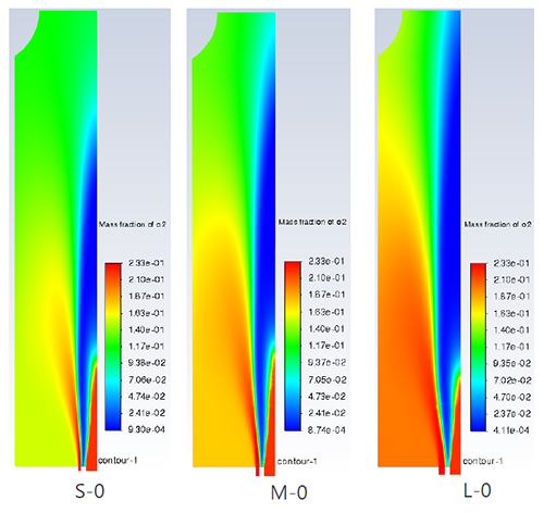
Figure 2 shows the elastic strain distribution of the tensile direction component at the time of performing the numerical material test in a direction perpendicular to the fiber in this model. We conducted a test of up to 30% macro strain, but when observing the strain distribution of the micro-scale, it could be confirmed that the tensile strain of 100% or more at vicinity of the fiber and approximately 10 percent of compressive strain had occurred in an area away from the fiber. Gradients of large strain localized in the model when performing the numerical material test on a model that had a large difference in rigidity, even a simple shape. Thus, there were cases that analyses could not be conducted frequently because of an element collapse as described above.
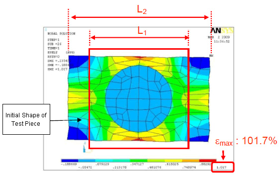
Figure 2.
The elastic strain distribution of tensile direction component
at macro strain (= L2/L1) of 30%
Figure 3 shows an animation of element collapse.
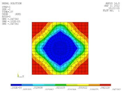
Figure 3.
Uniaxial tensile test response of material reinforced
in one direction using current version of Ansys elements
Comparison of numerical material test results by the new element formulation
Fiber composite material reinforced in one direction
A uniaxial tensile test was performed on the model in Figure 1 using the advanced element formulation※1 by Reese et al., Hannover University, which is newly added in CMAS4.1. Figure 4 shows an animation of the comparison of the results, and the results of low-order solid elements of the current version of Ansys. Abnormal end of analysis by element decay in macro strain of about 30% could not be avoided with the element type of the current version. However, it is possible to carry out a stable analysis, even when applying macro strain of 100% or more in the new type of element.
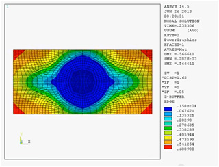
Figure 4.
Uniaxial tensile test response of material reinforced in one direction
(Ansys previous version element)
Click for Animation
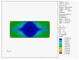
Figure 4.
Uniaxial tensile test response of material reinforced in one direction
(Newly developed element)
Click for Animation
Fiber-based composite material of ±90-degree alignment
We conducted a similar comparative verification using a ± 90 degree orientated model as shown in Figure 5. The material properties of fibers and matrix have adopted values similar to those of Figure 1.
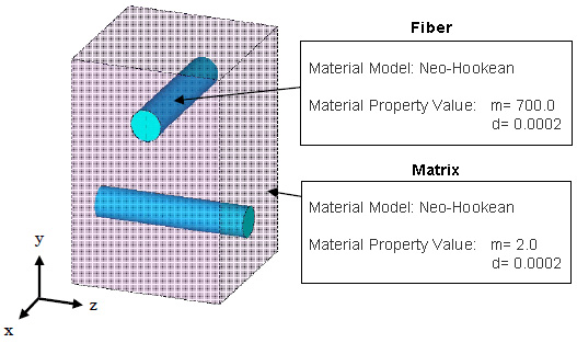
Figure 5. Fiber-based composite material of ±90-degree alignment
Figure 6 shows the state of deformation in the new type of element and the existing type of element respectively. Element collapse occurred in macro strain at 40% in the existing type of element, we were able to perform a very stable analysis at up to a macro strain of 400% with the new element.
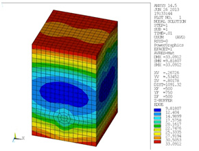
Figure 6. Uniaxial tensile test response of fiber orientation model
in ±90-degree alignment(Ansys previous version element)
Click to show animation
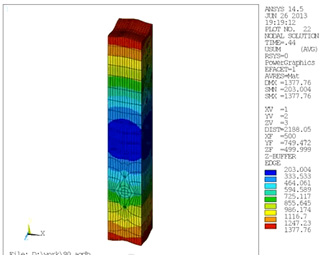
Figure 6. Uniaxial tensile test response of fiber orientation model
in ±90-degree alignment(Newly developed element)
Click to show animation
※1 S. Reese, P. Wriggers; "A stabilization technique to avoid hourglassing in finite elasticity"; International Journal for Numerical Methods in Engineering; Vol. 48, 79-109 (2000)
Analysis Types
関連情報
関連する解析事例
MORE

関連する資料ダウンロード
MORE-
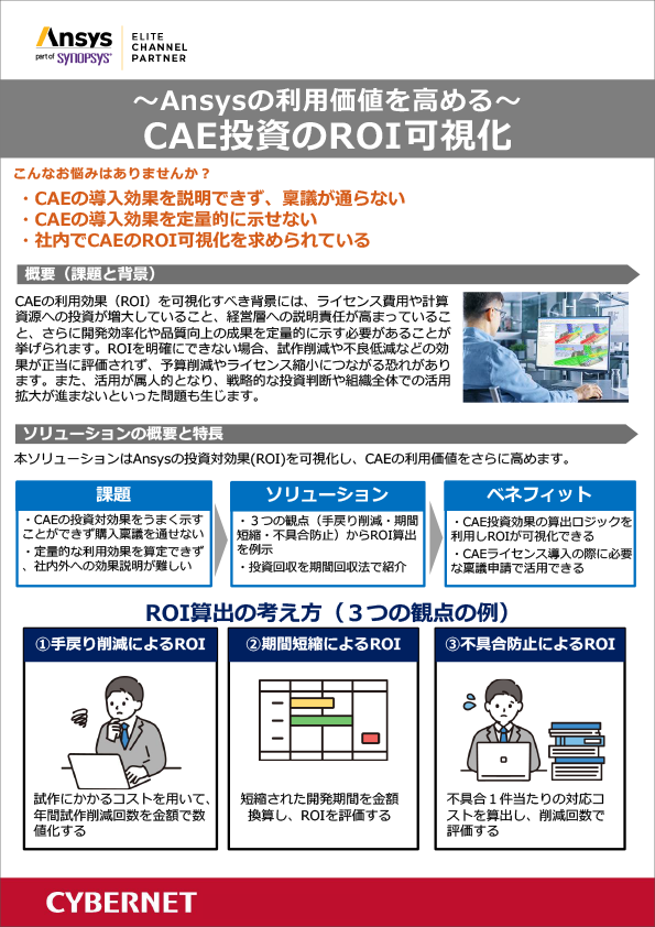
CAE投資のROI可視化でシミュレーションの利用価値を高める
-
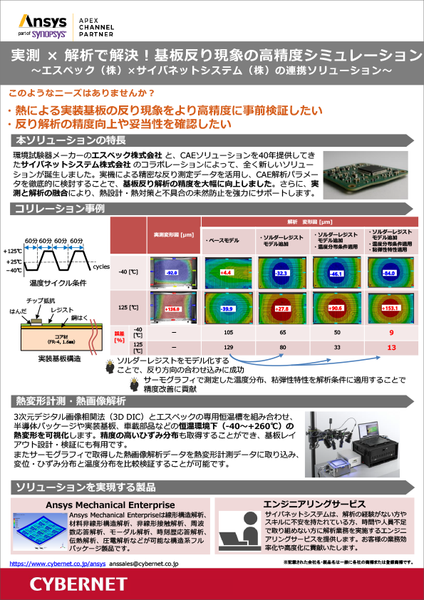
実測 × 解析で基板の熱変形問題を解決!基板反り現象の高精度シミュレーション
~エスペック(株)×サイバネットシステム(株)の連携ソリューション~
-
【全記事】CAEのあるものづくり vol.42
ユーザー様インタビュー記事7件を1冊に集約した保存版
-
誤差との上手なつきあい方 ~流体解析の計算誤差~ (完全保存版)
誤差との上手なつきあい方 前編・後編 を1冊にまとめた保存版 PDF
-
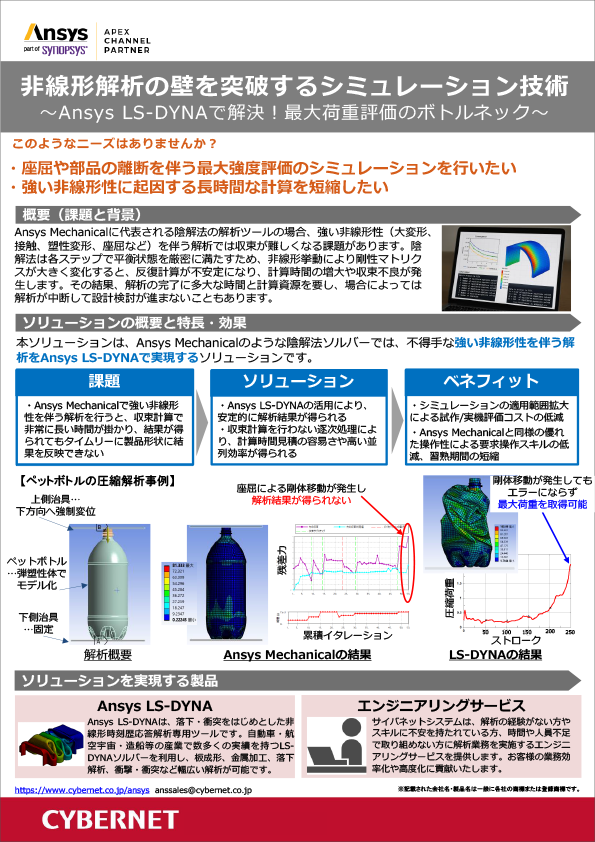
非線形解析の最大強度評価はAnsys LS-DYNAで解決!
~Ansys LS-DYNAで解決!最大荷重評価のボトルネック~
-

事例でご紹介!流体解析分野のエンジニアリングサービス ~解析業務の委託・立ち上げ支援・カスタマイズによる効率化など~
-
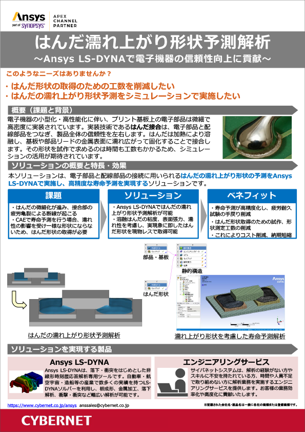
はんだ濡れ上がり形状予測解析で電子機器の信頼性向上
~Ansys LS-DYNAで電子機器の信頼性向上に貢献~
-
Ansys ユーザーのための PyAnsys 完全ガイド
Pythonで加速するCAEワークフロー