
製品
Simulation of fiber-based composites and validation of results: Fusion of actual measurement and virtual material testing.
Overview
Testing of carbon fiber reinforced materials can be difficult due to the complex structure and material behavior of the composite. To tackle this problem, researchers at Shimadzu and Cybernet Systems developed a workflow that compares CAE analysis results with the results of actual measurements of a fabric material.
This case study presents the CAE analysis workflow which starts with a carbon fiber reinforced thermo plastics (CFRTP) fabric material that was scanned using microfocus X-ray CT system to capture its internal structure. The scan data was reconstructed in Simpleware™ software to carry out multiscale analysis and simulate fracture behavior at the microscopic scale. By comparing the measured results from a testing system with the CAE multiscale analysis, it was possible to demonstrate the value of the technique.
Highlights
- Simpleware software used to reconstruct the internal structure of complex composite materials.
- Simulation using CAE tools for multiscale analysis such as Multiscale.Sim helps gain insight into materials performance.
- Methodology helps industry to combine measurement and analysis technologies for more efficient material and product design.
Introduction
Carbon fiber reinforced materials and other composite materials used for transportation can be designed to reduce weight and improve environmental performance. Due to the complex internal structures and anisotropic material behavior of composites, testing can be difficult, requiring a product design approach that combines actual measurements and simulation. This challenge is particularly key for fiber-based composites with complex material properties and deformation behaviors.
To tackle this problem, researchers developed a CAE analysis workflow that includes Synopsys Simpleware software as part of a process to compare CAE analysis results with the results of actual measurements. A carbon fiber reinforced thermo plastics (CFRTP) fabric material was scanned using microfocus X-ray CT system to capture its internal structure, and multiscale analysis carried out to simulate fracture behavior at the microscopic scale. By comparing the measured results from a testing system with the CAE multiscale analysis, it was possible to demonstrate the value of the technique.
Microstructure Generation
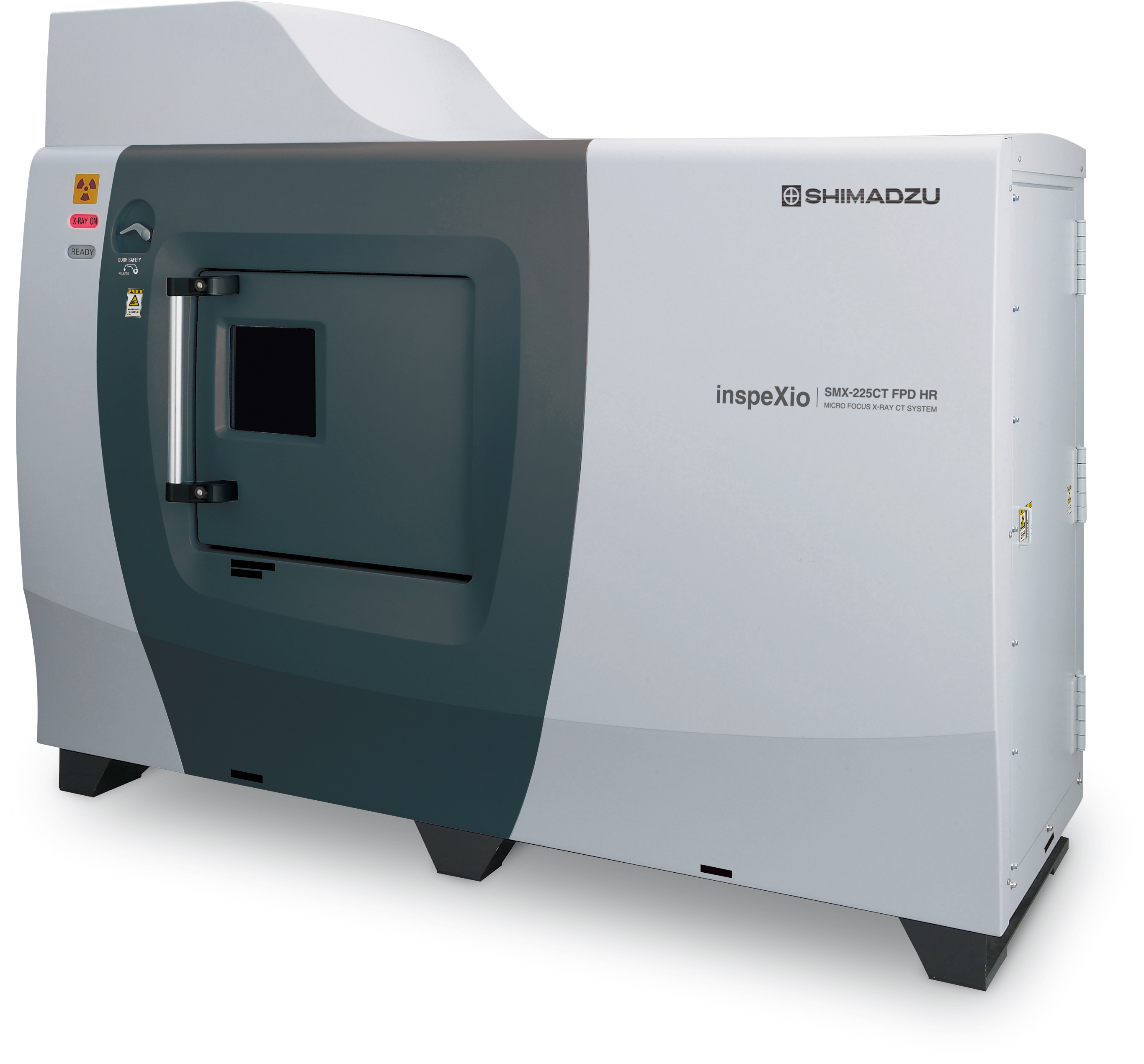
Microfocus X-Ray CT System
(inspeXio™ SMX™-225CT FPD HR, Shimadzu)
To predict material physical properties values using the homogenization technique, the shape of the microstructure for the analysis model needed to be given as a known quality. The Multiscale.Sim™ add-in tool for Ansys® software was used to generate models based on the shape parameters of the microstructure, with virtual material testing/numerical material testing (NMT) carried out on this default structural data (Model 1), and for structural data (Model 2) generated from a CFRTP fabric material using a microfocus X-ray CT system (inspeXio™ SMX™-225CT FPD HR, Shimadzu).
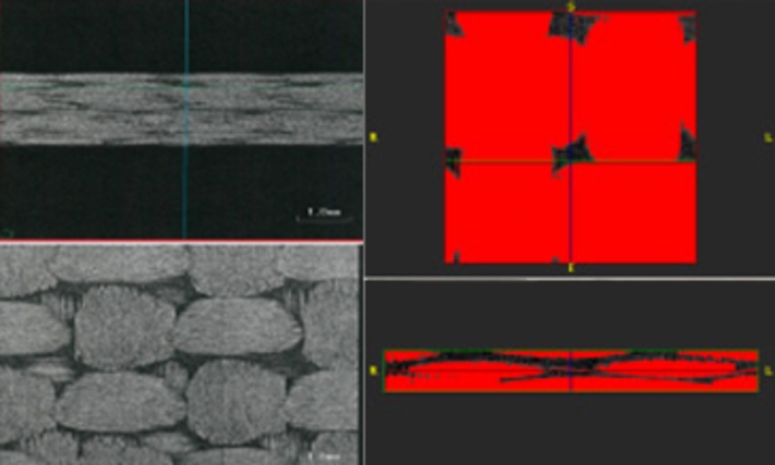
Figure 1.
Identification of microstructure shape parameters by
image processing in Simpleware software.
This image data was imported to Synopsys Simpleware software to identify the cross-sectional shape and the pitch and volume fraction of the fiber bundles. Virtual material testing was carried out in Ansys CAE software and Multiscale.Sim using a unit cell for different deformation modes and other conditions to acquire the elastic modulus of anisotropy in three directions from stress-strain characteristics for each direction. Furthermore, strain distribution at microscopic scale was measured through zooming analysis of the model of the rectangular test specimen.
Acquiring Actual Measurement Data
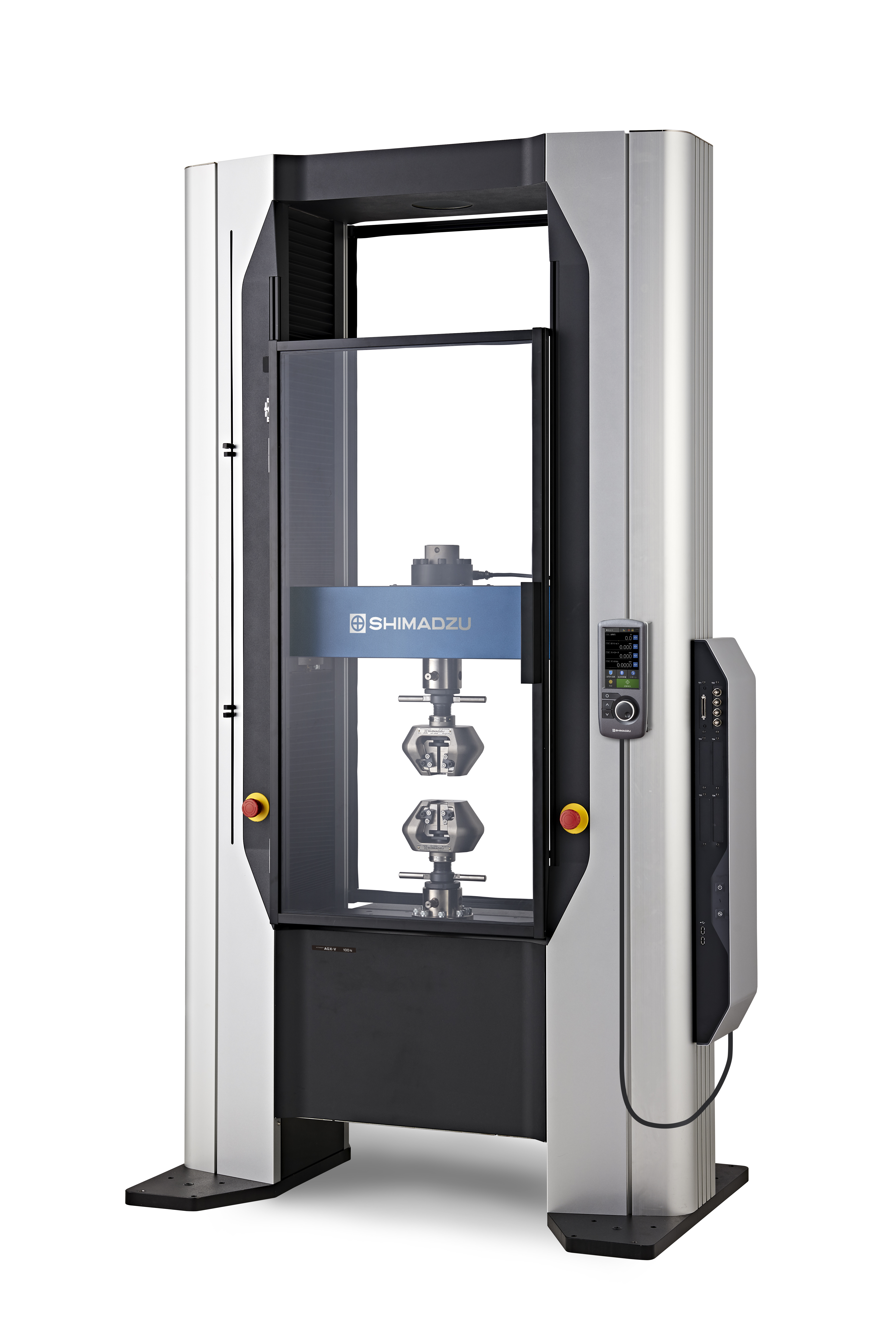
Precision Universal Testing Machine
(AGX™-V, Shimadzu)
Uniaxial tensile test (actual measurement) image data synchronized to loading was obtained from the test piece using a Precision Universal Testing Machine (AGX™-V, Shimadzu) and noncontact digital video extensometer (TRViewX (SP.1.0.0), Shimadzu). The modulus of longitudinal elasticity (Youngfs modulus) was acquired from the relationship of stress and strain, while the strain distribution of the test piece surface was captured using the digital image correlation (DIC) technique.
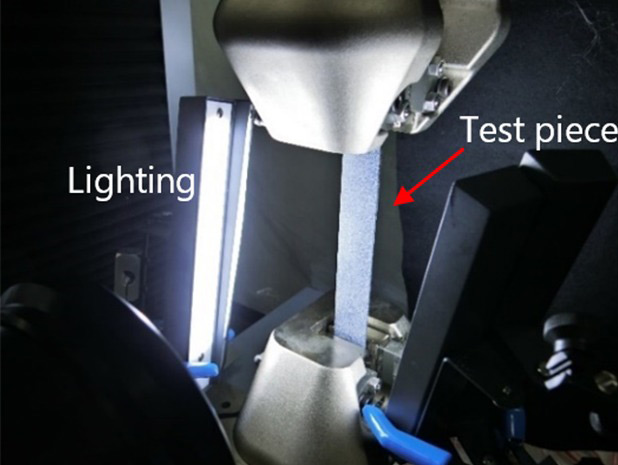
Figure 2.
Scene of uniaxial tensile test of a
CFRTP specimen.
To identify material constraints, MPR (Multi Planar Reconstruction) images of the test specimen were also acquired by arranging recorded CT images in virtual space to show images of any desired cross-section. This approach made it easy to observe the arrangement and interfaces of the carbon fibers.
Comparing CAE and Actual Measurements
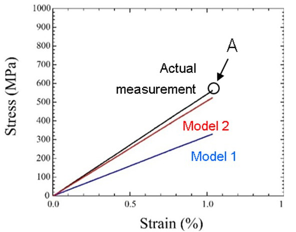
Figure 3.
Comparison of results of nominal stress-nominal strain curves in
actual measurement and CAE.
The two models from default structural data and image data were used for simulation, with the latter displaying non-uniform fiber bundles. A comparison was made of the elastic modulus identified by CAE/NMT and the uniaxial tensile test (actual measurement). Between the two results, the elastic modulus in the uniaxial tensile test was 55.46 (GPa), but 32.56 (GPa) for the default structural data, showing a large error. By contrast, Model 2 showed 51.75 (GPa), and was therefore closure to the measured value.
Conclusion
The analytical technique applied in the study is valuable for predicting the anisotropic behavior of composites by using a CFRTP fabric of a typical material. Verification of the internal structural model and actual measurements for validation of the analytical results showed the benefit of X-ray CT for enhancing the accuracy of CAE/NMT.
These methods are therefore able to predict very complex physical phenomena, such as in in anisotropic composites, and show the importance of combining actual measurements for comparison with computer-aided simulation. Ongoing work by the Japan Society for Computational Engineering and Science into High Quality Computing and standard simulation procedures are seeking to improve validation efforts, part of a broader international push for comparing actual and simulated results. From this approach, more efficient material and product design can be targeted.
Acknowledgments
Koji Yamamoto, Technology Specialist and Developer of Multiscale.Sim, Mechanical CAE Division 1, Cybernet
Systems Co., Ltd.
Takashi Murakami; Satoshi Iguchi; Zen Miyazaki, Analytical & Measuring Instruments Division, Shimadzu
Corporation.
Learn More
Download the full Shimadzu case study for more details regarding the comparison between the microscopic scale strain distribution of measured results and that of CAE multiscale analysis: Verification and Validation (V&V) of Uniaxial Tensile Test Simulation Results of Composite Materials: Fusion of Actual Measurement and Homogenization Analysis.