
製品
Predicting the strength of composite materials using Ansys Software and Multiscale.Sim - Applicable from material design to product design
Note: This article first appeared in EnginSoft Newsletter Summer Edition 2020
The term gcomposite materialsh refers to substances formed by combining two or more different materials into one. They have a long history: the earthen walls and earthenware seen in ancient buildings are splendid examples of composite materials made from straw and clay. Their greatest advantage is the ability to prepare new materials that have the characteristics and properties of their constituent parts. Earthen walls have both the toughness of straw and the heat resistance of clay. Alternatively, one can say that the problem of the strawfs highly combustible nature is mitigated by the clay.
Once using primarily natural fibers, composite materials today are widely used in many industrial fields since the emergence of carbon and glass fibers with their superior properties. In particular, the contribution of carbon fiber reinforced plastic (CFRP), which is a composite material made from carbon fibers and resin, has been remarkable in the aircraft field where the mandatory obligation of weight reduction has been met by taking advantage of the low density, high strength characteristics of the carbon. In addition, in recent years, its application has been actively increasing in the automobile industry where it is being used to reduce weight to improve fuel efficiency.
Consequently, composite materials have been receiving a lot of attention from industry, however, currently, the quantity of simulation results are significantly less than for metals. This article discusses some of the problems of using finite element method (FEM) simulation software for composite material analysis, and introduces the new solutions for solving these problems.
Problems in conducting composite material analysis
Compared to common metallic materials, composite materials have numerous significantly different properties. Here, we will address three typical and unique issues regarding composite materials that are important from an analytical point of view.
1. Material modeling
There are countless combinations of materials that make up composite materials. While this has the great advantage of expanding the range of material design, it has the problem that a general material database cannot be built like with metals. It is difficult and demanding to conduct a material test every time the combination of materials changes, and to prepare the material constants necessary for the analysis, with the result that the true usefulness of analysis, which lies in the low-cost trial-and-error testing of product designs, is nullified.
The main problem in obtaining physical property values lies in the fact that the material behavior is anisotropic. For example, in the case of fiber reinforced plastic, the rigidity of the fibers is higher than that of resin, meaning that the rigidity of the fibers in the orientation direction becomes much higher than in the orthogonal direction. In order to realize these material behaviors analytically, it is necessary to evaluate the rigidity in various tensile and pure shear directions by material testing, which is significantly more expensive than for isotropic materials.
Table 1 - Comparison of the general characteristics of metallic materials and composite materials
| Metallic materials | Composite materials | |
|---|---|---|
| Material behavior | Isotropic | Anisotropic |
| Material test | › (Easy) | ¢ (Difficult) |
| Material database | › (Many) | ¢ (Few) |
| Controllability of material properties | ¢ (Difficult) | › (Easy) |
2. Finite element modeling (FEM)
Composite materials also present specific challenges when it comes to creating finite element models. For example, there are composite materials in which the fibers are oriented in a continuous, straight direction, and composite materials in which fibers are woven into a laminated structure by layering thin sheets with different orientation structures in the thickness direction. In such cases, it is a common to change the laminated structure depending on the location in order to optimize the strength distribution of the structure. As a matter of course, when the combination of laminated structures becomes complicated, it is difficult to manage using only the modeling function of general FEM tools.
Furthermore, it is also important for the composite materialfs strength properties to be derived from the molding history. Simple images are shown in Fig. 1 and Fig. 2. Fig. 1 concerns injection molding and shows the fiber orientation when the resin with fibers is injected into the mold from different gate positions. The Planets X resin flow analysis tool developed by CYBERNET was used for the analysis. As can be seen, the fiber orientation of the final molded product depends largely on the gate position, because the fiber orientation is affected by the resin flow.
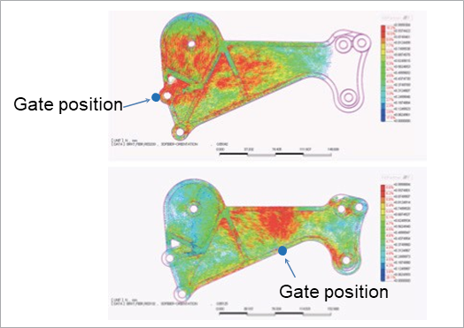
Fig. 1: Fiber orientation distribution of injection molded products based on the difference in gate position
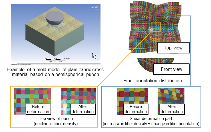
Fig. 2: Fiber orientation and fiber density distribution of press-molded fabric materials
Fig. 2 shows the fiber orientation of a flat sheet of composite material containing woven fibers when it is press-molded with a spherical punch. The explicit analysis tool Ansys® LS-DYNATM. was used for the analysis. Since the flat sheet has a strain distribution in the in-plane direction due to molding, it can be seen that the fiber orientation distribution and the fiber density are significantly different from those before molding. These problems show that unlike the isotropic behavior of metallic materials, it is not possible to obtain sufficient analytical accuracy even by defining the same material constants and material principal axes for the entire model.
3. Evaluation of fracture and damage
With the heterogeneous material structures found in composite materials, fracture and damage behavior are not easily simulated. This stems from the variety of fracture mechanisms. Some of the possible causes for the origin or progress of fractures and damage in fiber reinforced plastic laminates are a combination of the following:
- Interfacial delamination between fiber and resin
- Rupture of fibers
- Generation and progress of cracks in the resin
- Delamination between layers
- Various other factors.
Even if only crack propagation is taken into consideration, when hard materials such as fibers, etc. are present in the material structure, the crack growth is inhibited, so the propagation path strongly depends on the material structure. In other words, unless an analysis that considers the material structure is conducted, the fracture/damage behavior of composite materials cannot be predicted accurately, making it impossible to acquire knowledge for material design from the simulation results. The next section introduces new solutions developed by CYBERNET that use Ansys® Software to solve these three problems.
CYBERNET solution lineup to solve each problem
Here, we introduce two analysis tools that are effective in solving problems with composite materials.
Multiscale.Sim: Prediction of material behavior based on a model of the material structure
Multiscale.SimTM is an add-in tool for Ansys Software that was jointly developed by Nitto Boseki Co., Ltd., Quint Corporation, and CYBERNET SYSTEMS CO.,LTD. under the guidance of Professor Kenjiro Terada of Tohoku University. Its main purpose is to solve problems related to material modeling. By using the two functions of this analysis tool - homogenization analysis and localization analysis - it is possible to realize multiscale analysis in a way that considers the non-uniform material structure of composite materials.
Homogenization analysis - CAE as a material test device
Homogenization analysis can be used to acquire information to predict the physical properties of composite materials. Fig. 3 shows the flow of homogenization analysis. Here, an inhomogeneous microstructure of a composite material is prepared as an analysis model (hereinafter referred to as a micro model). In the case of a plain weave material, it supports the woven shape of the fiber bundle, and in the case of a particle-reinforced material, it supports the particle shape and the dispersion form.
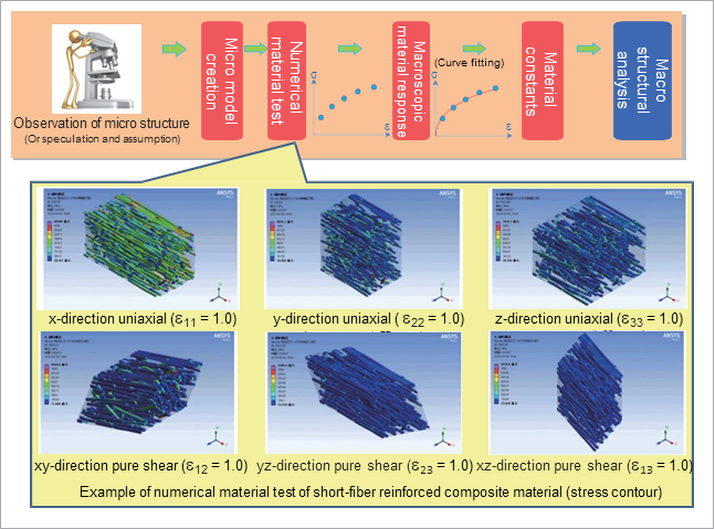
Fig. 3: Flow of material - identification of constants by homogenization analysis
Fig. 4 shows a typical example of a micro model. Templates are provided for automatically creating models of some typical microstructures. By performing a virtual material test (called a numerical material test) using FEM on the created microstructure, it is possible to obtain the apparent material response (such as the stress-strain characteristics) of the micro model. At this time, it is assumed that the micro models are periodically arranged in an infinite direction, and an ideal single stress field can be easily applied to the single unit cell model. The big advantage is that difficult pure shear tests can also easily be applied to simulations during real material tests.
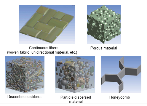
Fig. 4: Example of micro-model shapes
The material constants can be obtained by fitting the apparent material response thus acquired to the Ansys® MechanicalTM anisotropic material model. While the fitting function for anisotropic material models is not provided as a standard function in Ansys Software, it is implemented as a function in Multiscale.Sim. Material constants can be easily identified if material test data for each direction is available.
The information obtained by numerical material testing does not include only the apparent material response and the material constants. Since the microstructural inhomogeneities are actually modeled, the stress and strain distributions in the material can also be evaluated. Identification of the fracture mechanism is extremely important information for material design, but it can be said that it was obtained for the first time only by introducing this analysis method. Fig. 5 shows the results of a numerical material test performed by applying a material model of a fracture in the resin.
You can see that the cracks (transverse cracks) that occurred inside the resin are proceeding while bypassing the fibers.
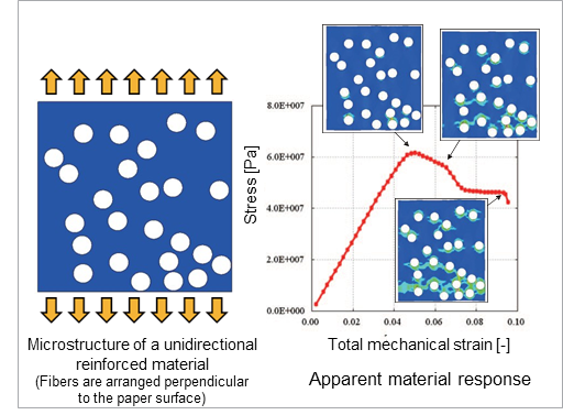
Fig. 5: Example of a numerical material test of a fracture
Localization analysis - CAE as a microscope
If the material constants for fractures in the composite material can be obtained using the homogenization method above, it is possible to estimate the occurrence of fractures in the actual structure, as well as various general fracture areas using different general-purpose CAE tools such as Ansys Software. However, it is not possible to estimate the specific factors of the fracture when analyzing a model in which an originally inhomogeneous material is replaced by a homogeneous material. This problem can be resolved using Multiscale.Simfs localization analysis feature.
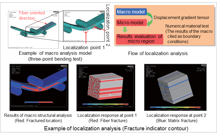
Fig. 6: Example of fracture mode observation based on localization analysis
The localization analysis function is introduced using a simple analysis example. Fig. 6 shows an example of a three-point bending test on a composite material. The sample is a unidirectional reinforced material in which the fibers are oriented in the longitudinal direction, and for which the fracture strength was acquired by homogenization analysis. It can be confirmed that the fractured regions shown in red are present on the bottom and top surfaces, as well as on the mid-surface of the sample. Localization analysis can be used to zoom in on parts of a homogenized analysis model to evaluate the material structure scale results.
Localization point 1 in Fig. 6 shows the localization result on the bottom surface of the sample, and localization point 2 shows the localization result on the mid-surface. Since the bottom surface of the sample exhibits a deformation mode in which it is pulled in the direction of the fiber, the fibers with a lesser rupture strain than the resin will break first, which results in a fracture of the composite material. On the other hand, since the shear deformation mode is dominant on the mid-surface, the fibers are hardly affected by the stress, and it can be confirmed that the fracture occurs due to the debonding of the fibers and the resin, and due to the expansion of the crack inside the resin. Identifying the cause of fractures using conventional CAE is difficult, therefore, and is one of the reasons why using CAE for the material design of composite materials is considered difficult.
The localization analysis function may, at first glance, seem similar to a sub modeling approach, but the major difference is that the two models being integrated have different size ratios. In the sub-modeling approach, the two models to be integrated must be of equal size, whereas in localization analysis, the size ratio is expected to be extremely large (see Fig. 7).
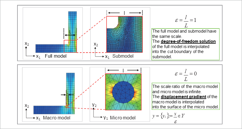
Fig. 7: Differences between sub-modeling and localization analysis
Ansys Composite PrepPost: FE modeling of laminated structures
Ansys® Composite PrepPostTM (hereinafter referred to as ACP) is a tool developed to efficiently implement the pre- and post-processing that is unique to composite materials. In this section, we introduce the pre-processing functions for the definition of laminated structures and the definition of the fiber orientation.
Definition of the laminated structure: From the definition method of the element unit to the definition method of the layer unit
The FEM analysis tool in Ansys Mechanical has always provided functions for defining laminated structures. However, it has certainly not been the most suitable modeling technique for defining the complex and large-scale laminated structures of actual structures in recent years. Fig. 8 shows the differences between these conventional tools and the ACP laminated structure modeling approach.
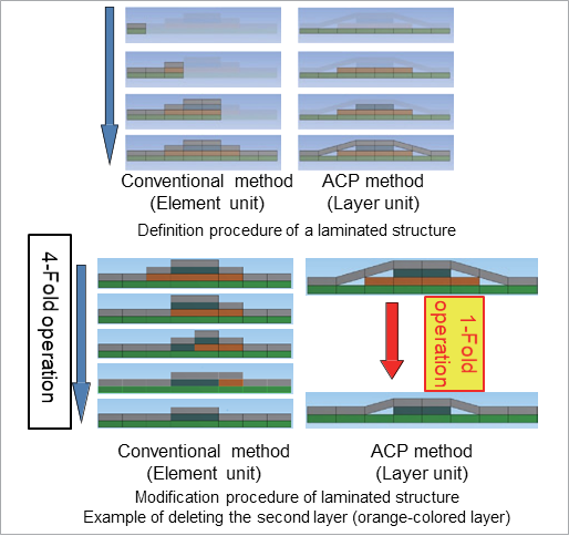
Fig. 8: Differences between the conventional method for defining laminated structures and the ACP method
In conventional modeling methods, laminated structures are defined on an element (or segmented surface) basis. When the laminated structure of each region is different, as shown in Fig. 8, it is necessary to define the number of layers in each region, the material constants for each layer, and the principal axis of each layer. On the other hand, the definition method in ACP involves specifying the layer units, and it is possible to stack arbitrary materials by specifying the region sequentially from the bottom surface. This procedure is similar to the creation process of the actual material, so the modeling can be performed intuitively, and the more complex the model becomes, the more efficiently the process can be applied with fewer menu operations compared to conventional approaches. These differences in specifications have a significant impact not only when defining the laminate structure, but also when making modifications. The composite material design process often involves trial and error tasks such as deleting certain layers, changing the material of layers, and interchanging the order of laminates. Even when such modifications are performed, operational efficiency is greatly improved by the ACP definition specifications. These sophisticated approaches to laminated structures improve work efficiency and play an important role in reducing the probability of human error.
Definition of the oriented direction: Departure from the definition method based on the local coordinate system
In an anisotropic composite material, the orientation of the materialfs major axis must be defined. The conventional Ansys Mechanical definition method for a materialfs principal axis is to create a coordinate system that specifies its orientation and which references the coordinate system in any family of elements. In the case of a model in which the materialfs principal axis is curved, a technique of arranging a cylindrical coordinate system at the center of the curvature and aligning the materialfs principal axis in the angular direction was used. While this can be very effective for simple, cylindrical models, it is necessary to create a large number of cylindrical coordinates when applying it to structures with complex curved surfaces, which is work intensive.
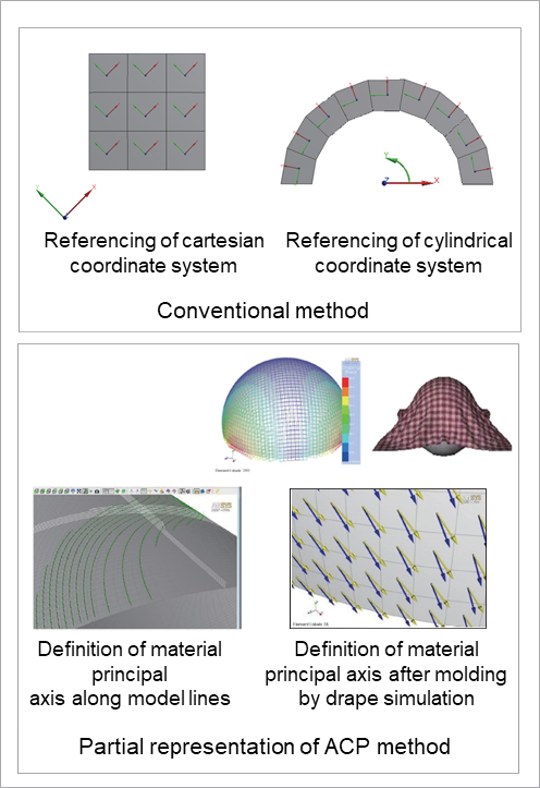
Fig. 9: Differences between the conventional method and the ACP method for defining a materialfs principal axis
On the other hand, the methods of defining the materialfs principal axis by ACP are extremely diverse, and were devised to handle the various complex geometric shapes found in composite materials. Fig. 9 is an example of a partial definition. It is also possible to define the materialfs principal axis along the lines that configure the model. This is an extremely useful tool for models with complex shapes. The drape simulation function in ACP enables engineers to predict changes in fiber orientation once a flat composite material is shaped on a curved surface; these results can also be used as the materialfs principal axis for structural analysis.
Conclusion
This article addresses three issues related to the analysis of composite materials using the finite element method: material modeling, FEM modeling, and fracture and damage assessment, and introduces the Multiscale.Sim multiscale analysis tool and Ansys Composite PrepPost pre-processing tool dedicated to composite materials, which are effective in solving these problems. There are many challenges in the analysis of composite materials, and it is necessary to combine multiple tools to solve them comprehensively. However, CYBERNETfs portfolio of composite material solutions is implemented on all Ansys® WorkbenchTM platforms, enabling seamless data integration and limiting tedious tasks to the bare minimum.
This time, we only introduced the function to predict the distribution of the fiber orientation using drape simulation as an analysis solution that considers the molding history. However, this is just one of many composite material molding techniques. At CYBERNET, we are continuously working on developing analytical tools and improving analytical technology for composite materials. In the future, we plan to introduce advanced analysis solutions for material design as needed.
Author: Koji Yamamoto - Technology Specialist and Developer of Multiscale.Sim
Analysis Types
Fiber reinforced Composite, Cross weave fabric, Press molding analysis, Multiscale analysis, Ansys composite preppost